Official GIGABYTE Forum

How to fit Front Plate USB Shield wire for Over Current on GA-MA770-UD3?

mikeym

  • 2
  • 0
Hi,

I'm using a GA-MA770-UD3 motherboard and I'm installing a front plate for USB / Audio Jacks. The USB plugs are 4 pin that go together in pairs to match 8 of 9 pin USB plugs on the motherboard. My motherboard manual shows the wiring as essentially the same as this:


The 2 USB plugs go on pins 1-4 and on 6-10, however they both have an extra separate pin called Shield that is to help with EMI and apparently helps with audio pickup from the USB that I get with it.

From what I've read[1][2][3] some motherboards have the 9th pin as an Over Current pin that I could attach a USB to:
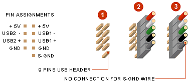


 But my motherboard show that pin as NC (like first diagram) for Not Connected. So how can I go about using these Shield pins with my motherboard? I've read suggestions to plug them in to the GND on the second USB 4 pin connection (pin 9 on the first diagram) so each USB port takes up a full 9 pin double USB connection, or to attach them directly to the case.

I would rather not melt anything so any help would be appreciated.


« Last Edit: February 23, 2012, 03:46:25 pm by mikeym »

Dark Mantis

  • *
  • 18405
  • 414
  • 10typesofpeopleoneswhoknow binaryandoneswhodont
    • Dark Mantis
Re: How to fit Front Plate USB Shield wire for Over Current on GA-MA770-UD3?
« Reply #1 on: February 23, 2012, 04:09:22 pm »
Hi and welcome.

It really doesn't make any difference where you attach them as long as it is at ground potential. So you could connect it to the chassis somewhere or anmy pin on the USB header that is marked ground.
Gigabyte X58A-UD7
i7 920
Dominators 1600 x6 12GB
6970 2GB
HX850
256GB SSD, Sam 1TB, WDB320GB
Blu-Ray
HAF 932

Gigabyte Z68X-UD5-B3
i7 3770K
Vengeance 1600 16GB
6950 2GB
HCP1200W
Revo Drive x2, 1.5TB WDB RAID0
16x DLRW
StrikeX S7
Full water cooling
3 x 27" Iiy

mikeym

  • 2
  • 0
Re: How to fit Front Plate USB Shield wire for Over Current on GA-MA770-UD3?
« Reply #2 on: February 24, 2012, 10:35:25 am »
Hi Dark Mantis, thanks.

How far could I push that? The nearest unused GND pin to the USB is part of the Chassis Intrusion Header which looks like this:

Code: [Select]
Pin No.    Definition
   1            Signal
   2            GND

And a bit further away the CD_IN connector has handily 2 GND pins:

Code: [Select]
Pin No.    Definition
   1            CD-L
   2            GND
   3            GND
   4            CD-R

As do SPDIF In and SPDIF Out:

SPDIF_IN
Code: [Select]
Pin No.    Definition
   1            Power
   2            SPDIFI
   3            GND

SPDIF_OUT
Code: [Select]
Pin No.    Definition
   1            SPDIFO
   2            GND